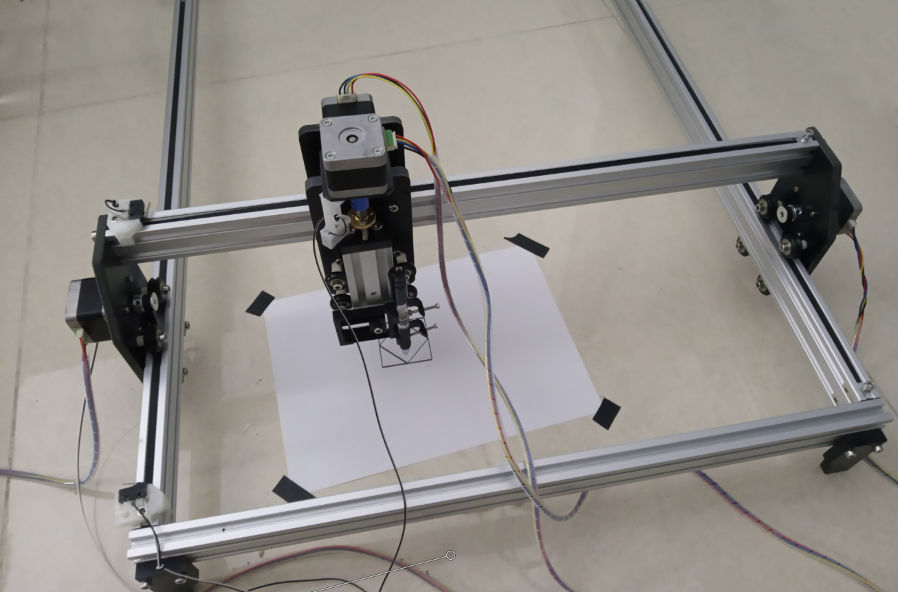
CARTMAN Bot Assembly Instructions
Keep in mind – Patience!
Read and think before act!
Step 1.
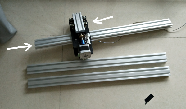
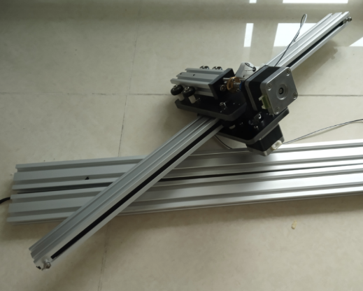
Find the 605mm-long aluminum rail (it’s slightly longer than the two 600mm rails and has threaded holes on both ends) and slide the X-axis cart onto it.
Step 2.
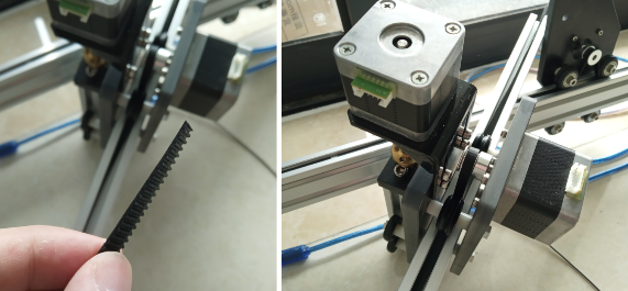
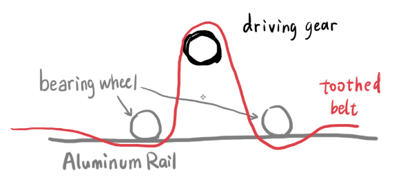
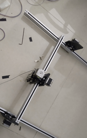
Route the toothed belt between the driving gear and bearing wheels like shown above.
Step 3.
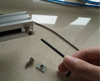
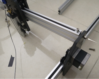
Fix one end of the belt to the same end of the aluminum rail, with a rectangular nut and a bolt, using the allen key.
Put something soft (paper?) under the belt to prevent it from tearing due to excessive pressure generated during the tightening of the bolt.
Step 4.
Now do the same for another end. Make sure the belt is slightly tensioned and the bolts on both ends are tightened. Cut excessive belt with a scissor.
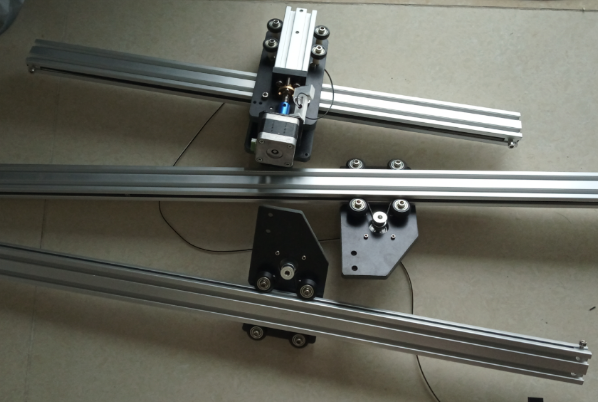
Do the same for the two Y-axis carts and their corresponding 900mm-long aluminum rail.
Step 5.
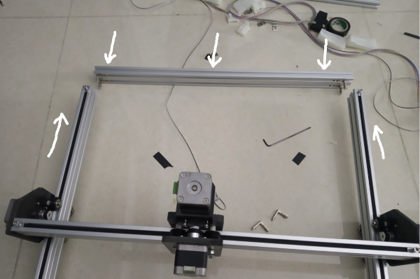
Join 3 previously assembled rails together using 4 bolts (note: don’t tighten them too tight until after step 6).
Step 6.
Now we want to join the shorter side of the rectangular frame with the two longer sides (Y-axis).
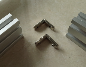
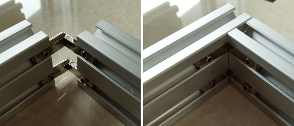
Find the right angle corners
You will have to install the screws (2 screws per piece) with an allen key.
They are used to join two rails together in 90 degrees. Simply fix the rails in place (with your hands or whatever) and tighten the screws and you’re done.
NEVER tighten all 4 screws in one pass; instead, slightly tighten each of the 4 screws before finally tighten them in a second pass. This is because the distance between each of the joining pieces changes as we tighten the screws, such that doing it in one pass will result in undesirably large gap between the two joining pieces.
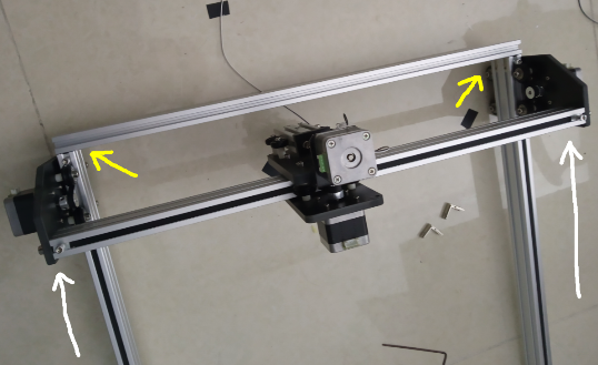
Before tightening the right-corner slots on one end of the machine (yellow arrows), push the Y-axis carts towards that end (white arrows) until they reach their limit. This way you won’t (after tightening the screws) make the rectangle too wide or too narrow for the Y-axis carts to travel smoothly.
Do the same for another shorter side of the rectangle.
Step 7.
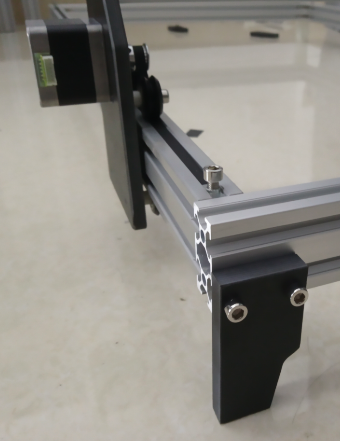
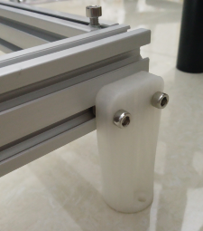
Install one foot on each corner of the frame (4 total).
Depending on your bot kit, there may be other options for the feet. Choose one that fits your purpose.
Step 9.
Don’t panic. You’re doing great!
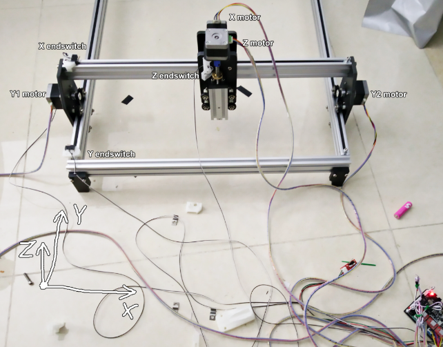
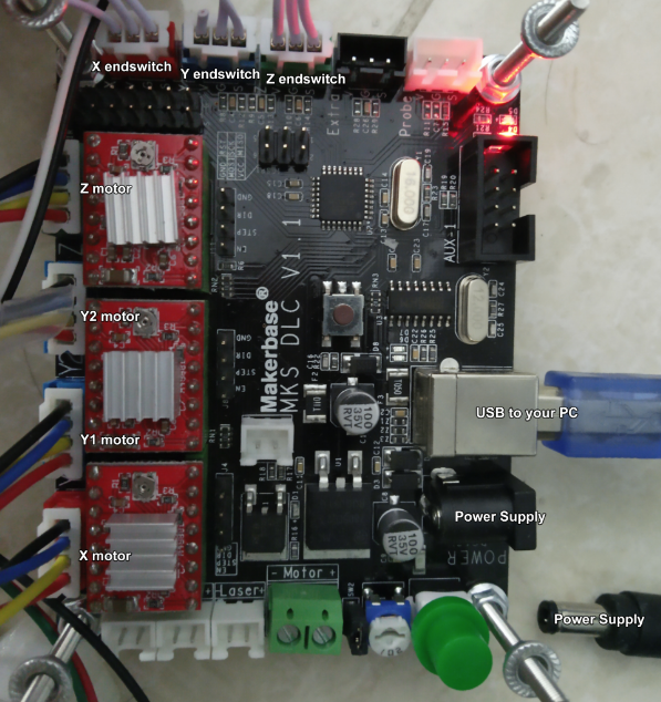
Calmly connect the 4 motors and 3 switches to the controller board.
DONE!
- Gradually tighten the bolt holding the pulleys if the cart wiggles on the rail instead of grabbing it firmly.
- The controller board runs Grbl v1.1 firmware and accepts G-code commands via a USB-Serial link. It’s based on a CH340 USB-Serial chip, check https://sparks.gogo.co.nz/ch340.html for drivers/more details.
The designer of the controller board chose CH340 instead of the better-supported FT232 or CP2102 or PL2303 because CH340 is much cheaper. (0.15USD/10pcs) - The controller board provides one PWM output capable of switching solid-state lasers. Which means the machine can be used as a laser engraver/cutter without modification. (you will need to buy the laser module yourself, though)
